Tabular (intermediate) results
Document history
- 2025-03-05: Updated for 2.7. Fixed typo, Total Fz is cumulative Fz, not cumulative Fx.
- 2025-04-19: Added diagram defining thrust offset columns. Added coordinate system and units sections.
- 2025-03-26: Clarified thrust and added sketch.
- 2023-05-26: Initial version.
Accessing intermediate results
A key feature of Archie-M is easy access to numerical calculation results, including all of the key calculation steps.
With a bridge model open, choose Tools -> Show tabular results...
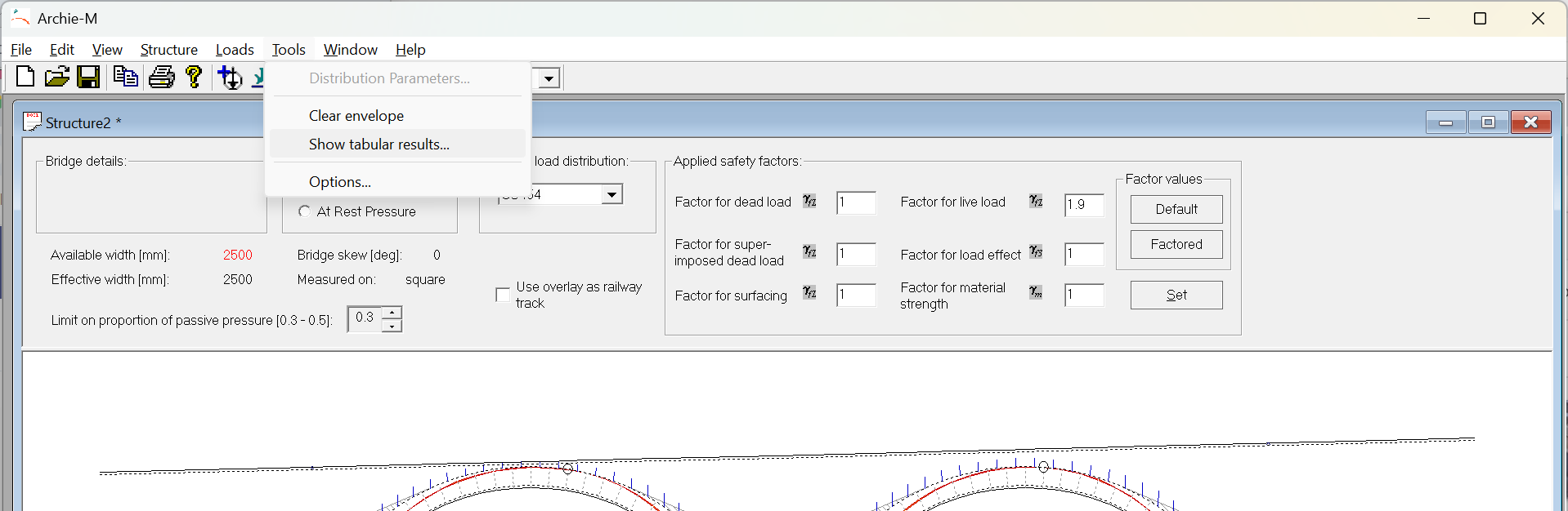
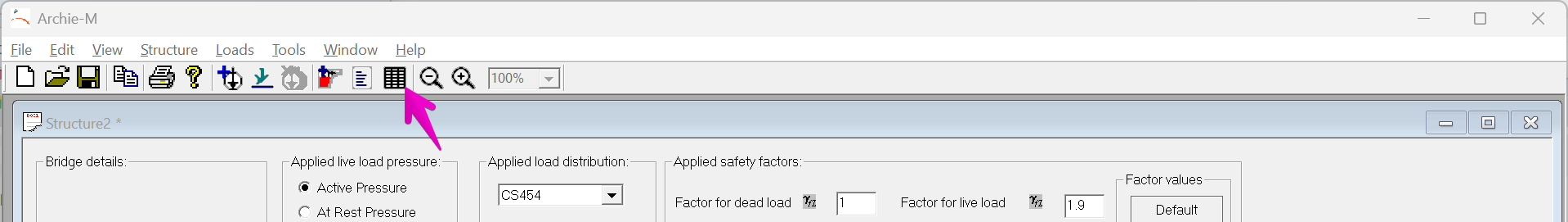
Alternatively, click the table icon in the toolbar.
Either will open a second window within the main Archie-M window. It is then possible to arrange the windows so both the graphical and tabular output are visible. The tabular output updates in real time as changes are made to the model.
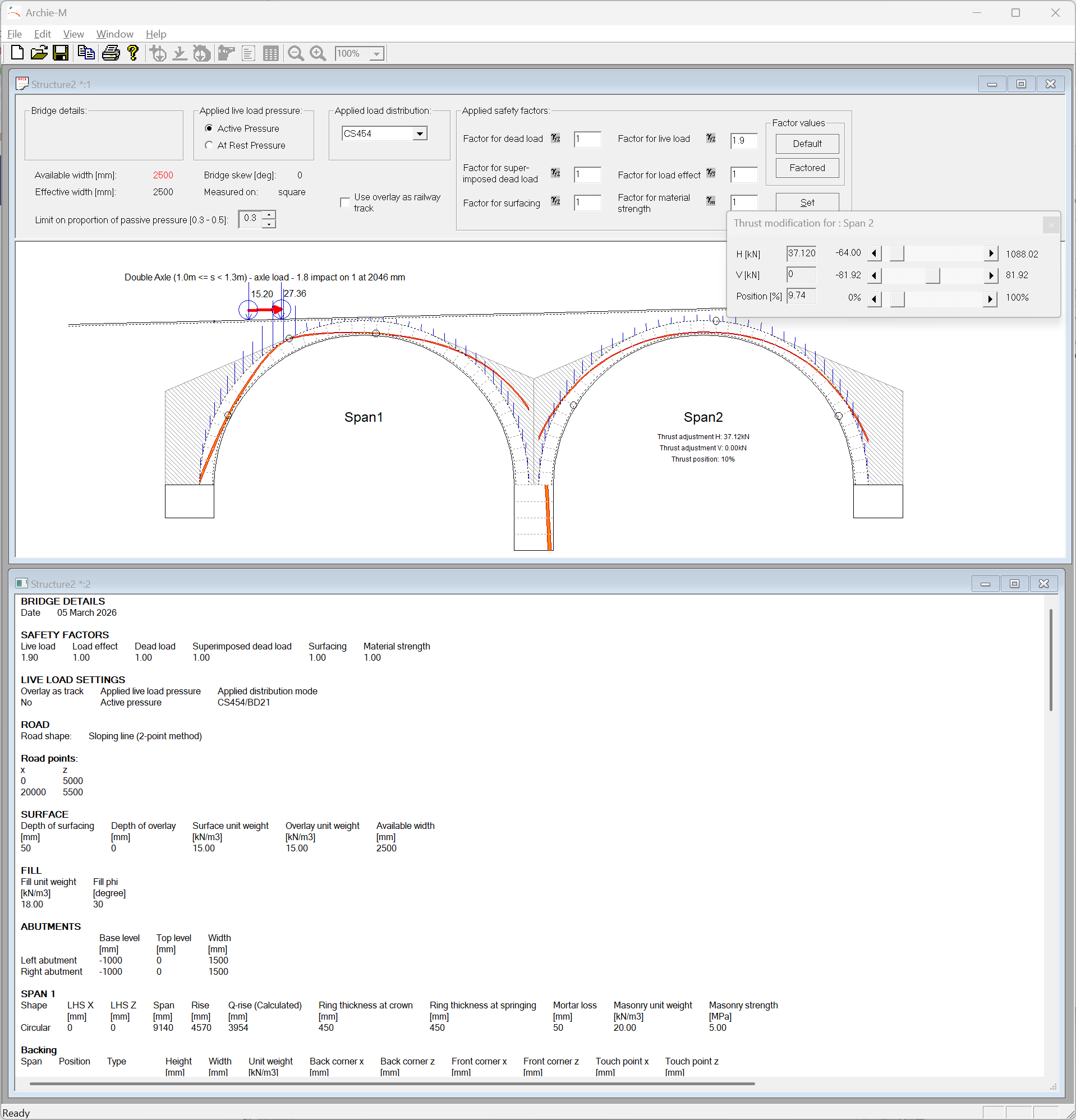
Maximising the text output will allow more of it to be seen at once.
Taking results to Excel
If you use Ctrl+C or Edit->Copy with a text view active, the content will be copied to the clipboard in tab separated format. This can be pasted directly into Excel, which can then be used to check results, or build on them.
With careful arrangement in Excel, it is possible to paste new output from Archie-M into the same location in Excel, to update calculations, eg for different load cases.
Coordinate system
The coordinate system used is right handed, y axis into the page, z axis up. Moments about the y axis are therefore positive clockwise.
Units
Dimensions are in millimetres, strengths in MPa (N/mm2), weights in kN/m3 forces are in kN per metre width, moments in kNm per metre width. From version 2.7, units should be stated everywhere.
Content of tabular results
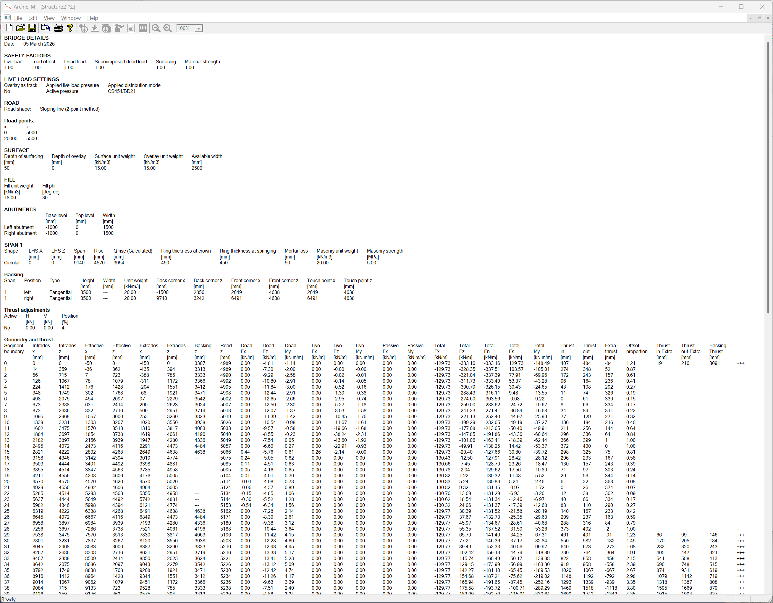
The structure of tabular results was slightly updated for 2.7 to be more comprehensive and better organised.
The structure of the results is shown below across two screenshots.
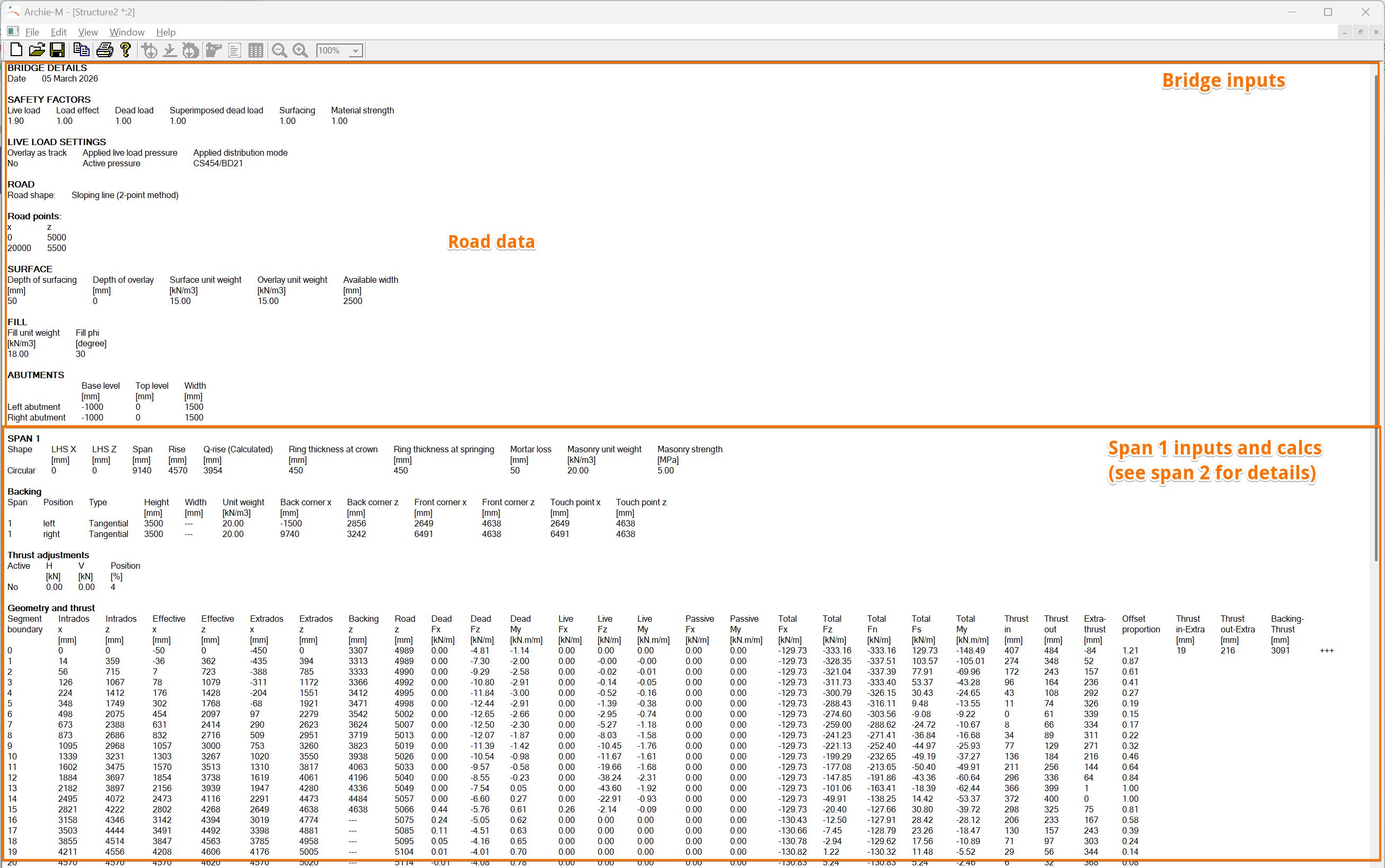
The first sections repeat global inputs. Spans and piers then have a block each, moving from left to right as shown on screen in the graphical view.
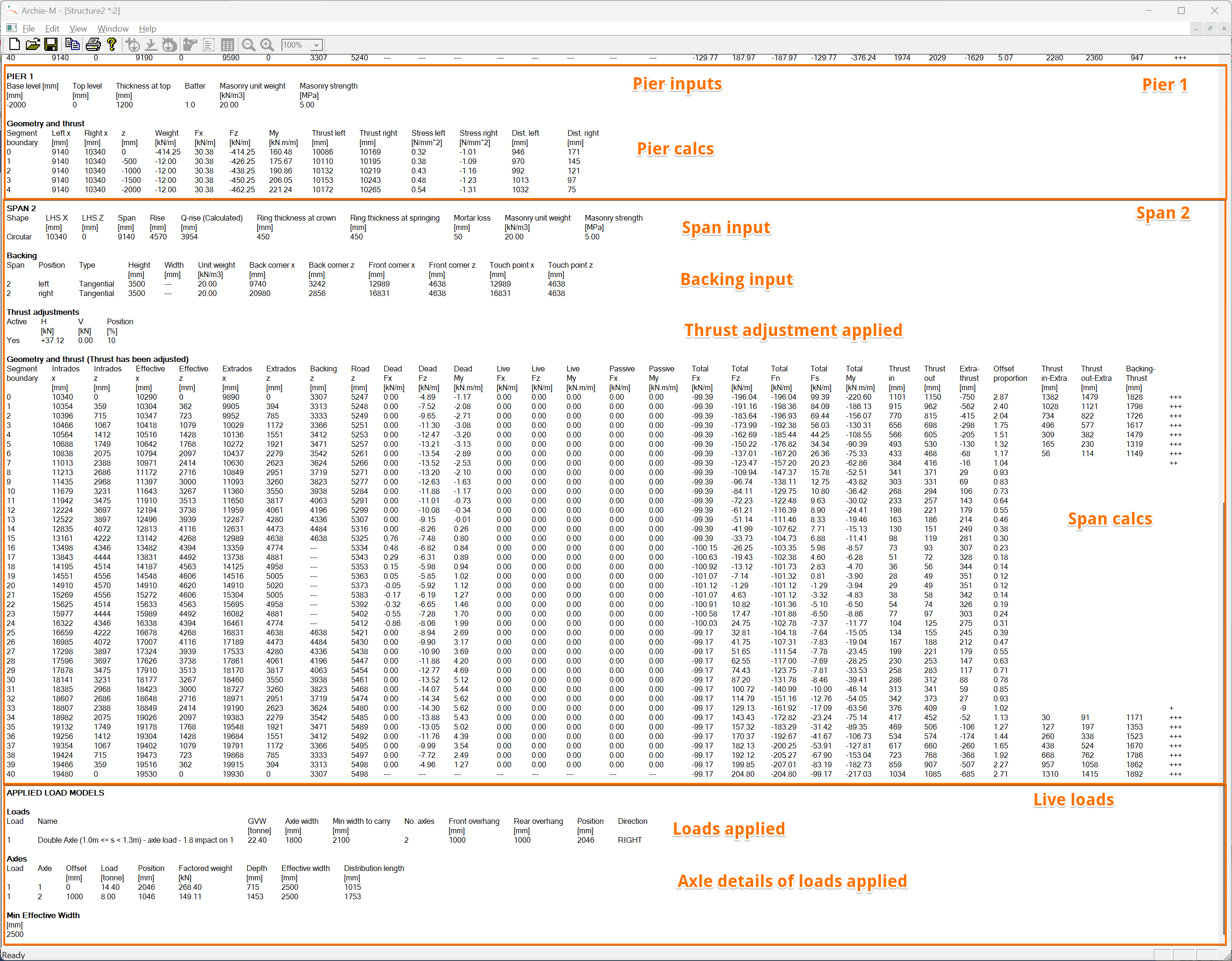
In each span and pier block, the input data for the item are given first, then the calculations.
Both spans and piers are divided into blocks, or "segments". By default there are 40 segments per arch. The number of segments in the piers depends on the pier height.
The calculations, are organised by segment boundary. If there are n segments, the number of segment boundaries is n+1. The line numbered 0 is the left springing, 1 is to the right of the leftmost segment, and so on.
Span results columns from left to right are:
- Row (segment boundary or segment) number.
- Intrados node x coordinate.
- Intrados node z coordinate.
- Effective intrados (after mortar loss) node x coordinate.
- Effective intrados (after mortar loss) node z coordinate.
- Extrados node x coordinate.
- Extrados node z coordinate.
- The z coordinate of the top of backing directly above the extrados node (where applicable).
- The z coordinate of the road directly above the extrados node.
- Dead load Fx. The increment of force in the x direction added by the segment to the left of this boundary. Incremental forces in the x direction would arise from horizontal soil pressure. The values for the first row are 0 because there is no segment to the left.
- Dead load Fz. The increment of force in the z direction added by the segment to the left of this boundary, from segment self weight, and the weight of backing, fill etc above. The values for the first row are 0 because there is no segment to the left.
- Dead load My. The increment of moment at the intrados about the y axis (clockwise positive) contributed by this element and the material above. The values for the first row are 0 because there is no segment to the left.
- Live load Fx. Force x component from live load on segment to left.
- Live load Fz. Force z component from live load on segment to left.
- Live load My. Moment at intrados, about y axis, from live load on segment to left.
- Passive pressure Fx. Additional Fx from passive pressure for segment to left.
- Passive pressure My. Additional My from passive pressure for segment to left.
- Total thrust Fx. The cumulative total Fx at segment boundary, summing from the right reaction.
- Total thrust Fz. The cumulative total Fz at segment boundary, summing from the right reaction.
- Total thrust Fn. The total thrust component normal to the segment boundary (aka axial component of thrust). Derived from Fx, Fz by rotation.
- Total thrust Fs. The total thrust component along the segment boundary (aka shear component of thrust). Derived from Fx, Fz by rotation.
- Total thrust My. Thrust My - the cumulative total My at segment boundary intrados, summing from the right reaction. Note that moments are shifted to new location at each step of accumulation.
- Thrust in. Offset of inner edge of zone of thrust from intrados point along segment boundary.
- Thrust out. Offset of outer edge of zone of thrust from intrados point along segment boundary. Line of thrust lies at the midpoint between thrust in and thrust out.
- Extra[dos]-thrust. Offset along the segment boundary from extrados to outer edge of zone of thrust. A value less than zero indicates that the zone of thrust is outside the arch ring (but may not be outside masonry if backing is present at this location).
- Offset proportion. The ratio of (Extra-thrust) to effective ring thickness (ring thickness less mortar loss) at this boundary. An offset proportion <= 1.0 indicates that the zone of thrust is fully within the arch ring masonry. The offset proportion reported in autorun is the worst of these values for the worst case load position.
- Thrust in - Extra[dos]. Values given where backing is present above extrados point, and where thrust is out of the arch ring. The vertical offset from the inside edge of the zone of thrust to the extrados. Positive values indicate that the zone of thrust is entirely outside the arch ring masonry.
- Thrust out - Extra[dos]. Values given where backing is present above extrados point, and where thrust is out of the arch ring. The vertical offset from the inside edge of the zone of thrust to the extrados.
- Backing - Thrust. Values given where backing is present above extrados point, and where thrust is out of the arch ring. The vertical offset from top of backing to upper edge of zone of thrust. Values below zero indicate that the thrust is above the backing.
- Unlabelled. Rows are marked with +++ where the zone of thrust runs outside the arch ring *** where the zone of thrust is touches or falls outside the extrados.
All forces and moments are per unit (metre) width.
The dead load columns include the self weight of the arch segment and the weights of backing, fill, surfacing, and overlay in the column directly above that arch segment.

The triple (Fx total, Fz total, My total) is the thrust at the segment boundary. Thrust is defined on the face to the right of the boundary but the components are in the global coordinate system (x positive right, z positive up, moments positive clockwise). At the rightmost segment boundary, the thrust is the reaction from the abutment on the arch, and you will typically see a -ve Fx and +ve Fz. At the leftmost segment boundary, the thrust is the force applied by the arch on the abument, typically -ve Fx, -ve Fz. To get the left reaction, negate both Fx and Fz.
The diagram below illustrates the meaning of Thrust in, Thrust out, and Extra-Thrust. Note that the average of Thrust-in and Thrust-out is the centre of the zone of thrust, or the position of the traditional line of thrust.

Some applications
Thrust at springings
The horizontal component of thrust at the springings (per metre width) can be read directly from the first and last rows of the span data, in Fx total. Similarly for vertical loads from Fz total. Note that the values in the last row of the table are the reaction at the right abutment (the force from the abutment on the arch), while the values in the first row are the force applied by the arch to the abutment. Check your signs.
These results include any thrust adjustment applied.
Shear/axial ratio
From Archie-M version 2.7 (documented here), the tabular results include Fn (normal or axial force) and Fs (shear force), but not the ratio. Copy the tabular results (Ctrl-C in the tabular results window, no need to select anything) and paste into excel. The data will paste into cells and allow you to make this calculation.