Multi span viaducts
Document History
- First version, 2023-05-26
Viaduct behaviour
Soon after the first version of ARCHIE was released, requests mounted for a way to assess structures with more than one span on relatively slender piers. This led to the introduction of MULTI. The capabilities of ARCHIE and MULTI were merged with the release of Archie-M.
The behaviour assumed for multi-span structures was that of flexible arches on flexible piers. There is now considerable evidence that this assumption is flawed. The stiff block of masonry over the pier does not arch, and the resulting behaviour is that of a cantilever and suspended span structure. Those assessing multi-span structures should consider the implications of this, particularly if assessing for a significant change in loading.
The remainder of this page discusses the modelled behaviour of flexible arches.
Indeterminacy
A single span masonry arch is statically indeterminate, with three unknowns. Each set of values for the three unknowns will produce a different line of thrust.
It has long been understood that, if we can assume that sliding and crushing will not occur, stability of an arch requires only that the thrust can fit within the masonry. The question of what the "true" thrust is has exercised many great minds, but is not actually a meaningful question. We must only show that some thrust fits.
There are two limiting cases. The minimum energy thrust occurs when hinges form in the pattern intrados/extrados/intrados. The exact positions will depend on arch geometry and loading, they are shown here at springing/crown/springing for simplicity.
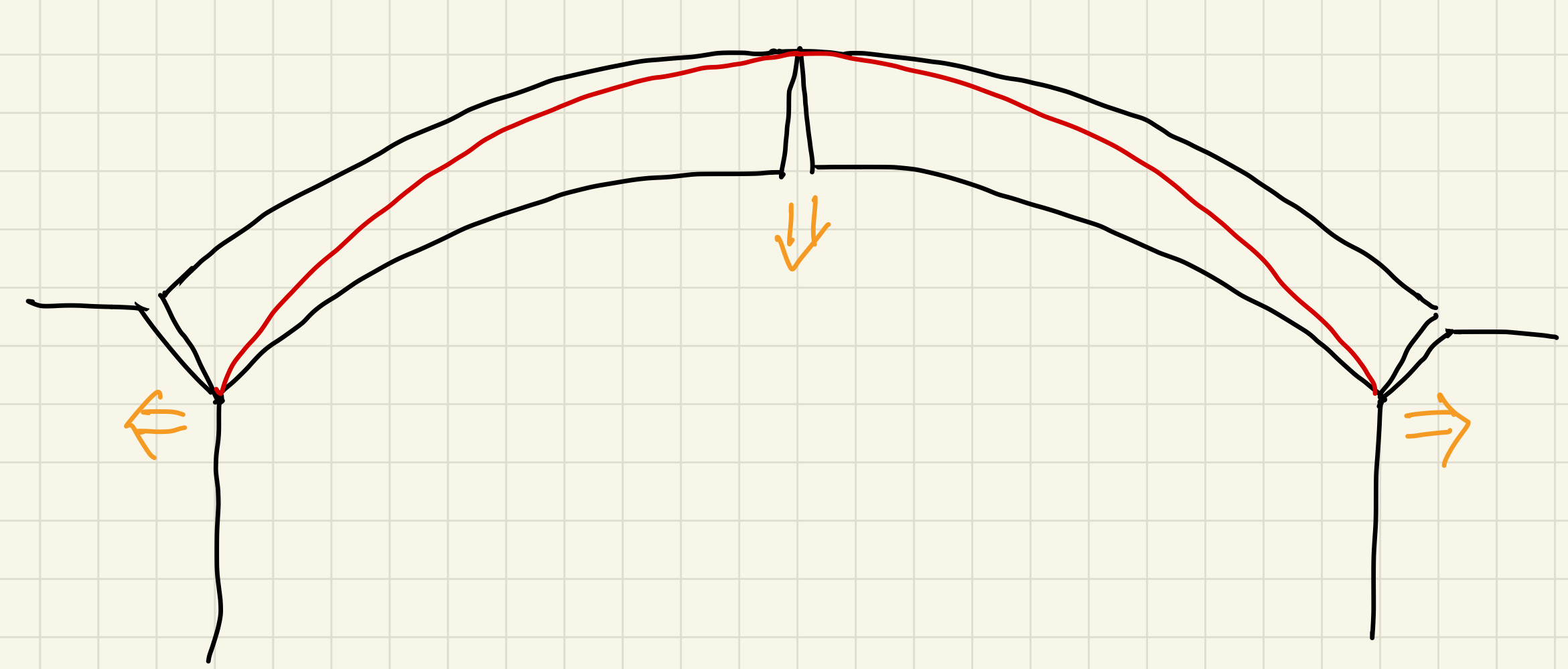
The maximum energy thrust, and the highest possible horizontal thrust, occurs when hinges form in the pattern extrados/intrados/extrados. If backing is present (it usually is) then the thrust can rise further at the outer ends.
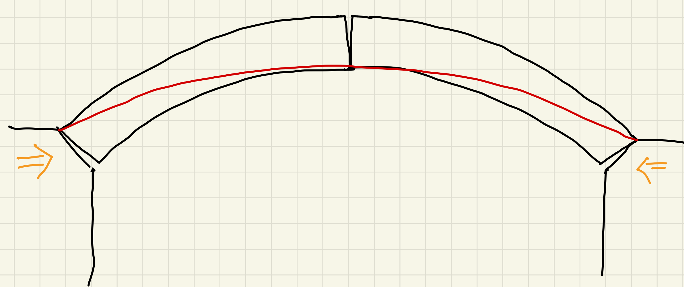
In these limiting situations, the structure is no longer statically indeterminate. It has become a three pinned arch.
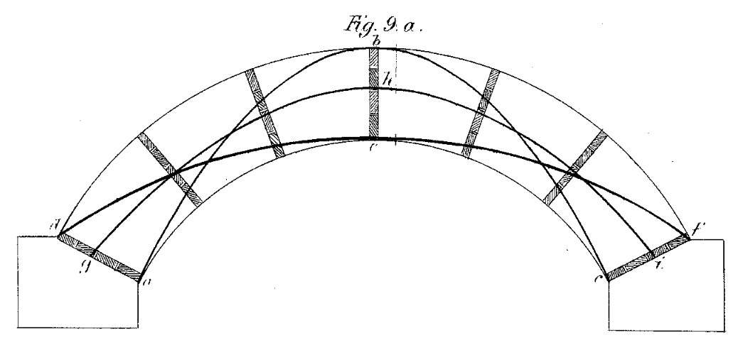
Between these, there is an infinite range of possible thrusts. Barlow showed this in a physical model.
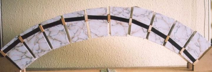
Bill Harvey built a similar model, showing that asymmetric thrust is equally valid.
The movements required to go from minimum to maximum energy state, are very small, assuming there has no gross movement causing open cracks as sketched above.
Single spans
When looking at single spans, for a given load position, Archie-M optimises the thrust to find the minimum stored energy that still allows the thrust to fit within the masonry.
This is also a most probable thrust, because the normal behaviour when the temporary centring is removed from an arch at construction is that the abutments give slightly. That causes the span to increase very slightly, which moves the thrust towards the low energy state, with lower horizontal thrust component. The thrust from the arch decreases as the available reaction from the abutment increases. Movement stops when equilibrium is achieved, as long as the minimum thrust is lower than the maximum resistance from the abutment.
Multiple spans
With two spans on a pier, each span has its own minimum energy state, but unless the spans are symmetrical around the pier, the horizontal thrust in each case will be different. The pier is flexible, so the span with higher thrust will tend to expand, squeezing that with lower thrust. As this happens, the higher thrust will reduce, and the lower will increase, until equilibrium is achieved.
If a load is applied in one span, the minimum energy thrust in that span will change. The neighbouring spans will adapt to achieve equilibrium. As loads move over the structure, the spans continually rebalance.
Archie-M does not currently attempt to undertake this balancing. It finds the minimum energy thrust in each span, then stops. If thrust fits in the masonry in all spans, but does not fit within the piers, the assessor must then "modify thrust" to check that pier thrust can be brought back into the masonry.
As an example, consider a viaduct with 4 spans, all elliptical with rise 8ft () and ring thickness 450mm. Spans 1, 3, and 4 have span 24ft (), while span 2 has a longer span of 32ft (). The dead load thrust looks like this:
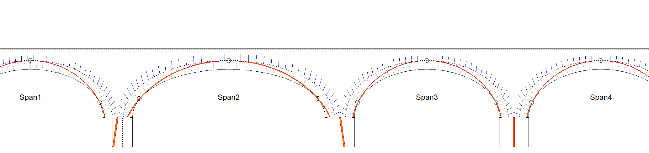
Notice how between spans 3 and 4, which are identical, the pier thrust runs straight down the middle of the pier. Either side of span 2, in contrast, the pier thrust slopes, indicating that the horizontal thrust component from each side of the pier is imbalanced. In this case, the imbalance is within the capacity of the pier.
We apply a live load to span 1, positioned for the worst effect on pier 1. The pier thrust is still within the masonry.
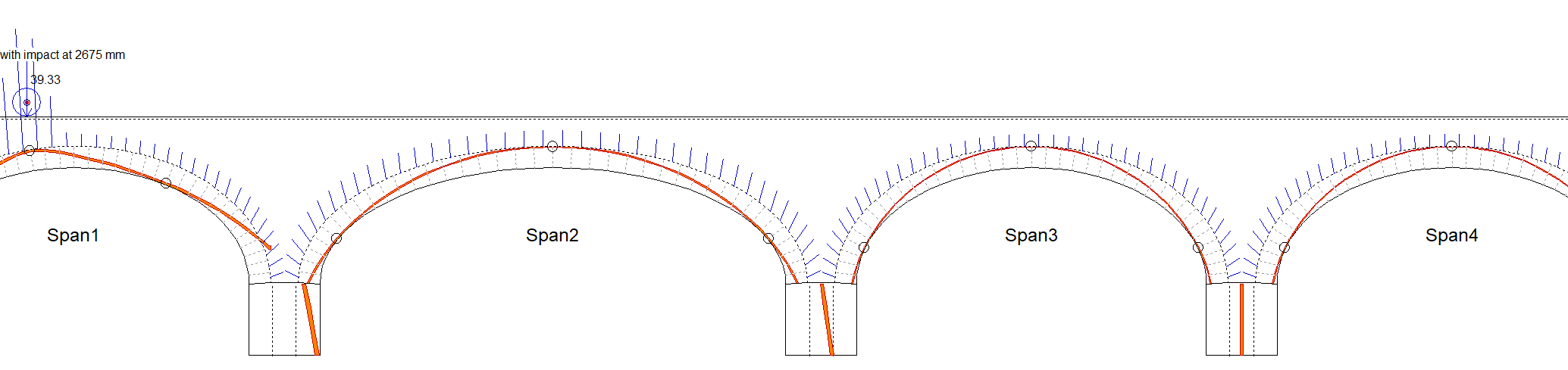
We move the load to the same position in span 3. Now the pier thrust to the right escapes the pier.

Why did that happen here and not with the load in span 1? Because in span 1, the larger horizontal thrust from span 2 helps balance the pier. Span 4 does not provide that. The escape is small, and would be easy to resolve using thrust adjustment, but lets look at that where it is more difficult.
Move the load to span 2, and position to have the worst effect on pier 2 to the right.

This is a typical situation you might find after using autorun. Archie-M should indicate "ADJUST" in the autorun results for the pier worst case.
To adjust thrust, right click on span 3, and select "Modify thrust...".

The modify thrust dialog has three slider controls.

With it, we can adjust the unknowns for the thrust in span 3.
The main thing is to increase the horizontal component, H. We would normally also need to lower the position, bringing the thrust down over the crown to just touch the intrados.

Now the pier 2 thrust is inside the pier, but we have to issues to address. Pier 3 thrust is now not within the pier, and the span 3 thrust is escaping from the arch well above the springing.
Taking the latter first. The span 2 thrust escapes the ring even in the dead load case. There is certainly some backing here. Lets add a typical viaduct backing arrangement of tangential backing creating a valley over the pier for drainage.

Adding backing appears to reset the thrust adjustment. A click first one arrow then the other on any of the thrust controls will restore the previous settings.

The arch thrust is now comfortably contained by stiff backing. Notice that the thrusts have changed slightly, this is the result of the changes in density and behaviour of backing vs. fill.
A further tweak will bring pier 2 thrust back in, but what about pier 3? There are three possible responses to this, to be used alone or in combination.
We can fix the adjustment of H in span 3, and also adjust span 4. Right clicking on spans allows you to open thrust adjustment in as many spans as you need at the same time.

This works here because there is an abutment to the right of span 4. If there were more spans, you might find that this resulted in pier 4 thrust escaping.
To minimise how far live load effect propagates, it is possible to adjust the V parameter of thrust. This skews the thrust, and increases the influence on pier thrust at one end of the span relative to the other.

Sometimes this is enough to stop the live load effect propagating to the next pier. In our case, limited backing and elliptical arch geometry means it doesn't have as big an effect as we would need.
The main response needed is engineering argument. We are constrained by the model enshrined in the assessment standards, and what can be modelled in 2D. The effective width limits transverse distribution of live load based on the shallowest axle. It is not a defensible model even for single span bridges, where it was conceived. It is ridiculous on multi span structures. Furthermore, most masonry bridge include elements that are very stiff longitudinally, much stiffer than the arch barrels, particularly the spandrel walls. Force follows stiffness, and these elements would pick up the thrust before it propagated multiple spans.
If numerical comfort is needed, it might be found by making a modified load file, with an axle load, and set the axle width to the full bridge width. This cannot be used to assess in the loaded span, but it will give you a slightly more realistic view of the effect of that load in more remote piers.
For this reason we recommend modelling sets of three or at most four spans. If you want to find an overall worst span in a run, then use autorun on a longer model to work out which span that is, then switch to a more limited model with that span and its neighbours.