Thrust
What is thrust?
Much discussion of masonry bridge assessment and analysis talks of "thrust", and the line of thrust is central to assessment with Archie-M. It is important to understand this concept.
Think of a single arch standing on its abutments, supporting its own weight. The arch is built over a timber "centre" (temporary formwork).
 When the arch is complete and the centre removed, the weight of the arch (and any fill etc over it) will push out on the abutments. The crown will drop slightly and the span increase. Fine cracks will open as shown (exaggerated).

The opening of these three cracks is helpful to us here, at it removes for the moment the complication of statical indeterminacy. When cracked like this, the structure is determinate. Given geometry and material weights, we can calculate the reactions.
At the cracks, it is obvious that there is no stress where the crack is open. All the force must pass through the contact area. In the sketch, this looks as if that might be a point, but a little local crushing of stone or (most often) mortar will maintain the area to keep the contact stress down. At these points, we assume a uniform stress distribution at the edge of the ring, just wide enough that the stress does not exceed the material.

Between the cracks, the stress must change gradually between these extremes. If we cut the arch at particular locations away from the cracks, the distributions might look as shown below.

The resultant of the normal stress at each cross section is a force, which acts at the centroid of the stress distribution. If we connect these points around the arch, this is the line of thrust.
We assume that masonry cannot sustain tension. This is not quite true in general, but is close, and the assumption is safe. In the right hand example in the last figure, this is reflected in the fact that the stress distribution runs out to zero in the depth and then remains zero, rather than becoming negative.
On the other hand, compressive strength is high. If we also assume linear stress distribution, the range of possible situations in a given section look like this.

From left to right:
- Thrust (= centroid of stress) is at the limit, the stress is uniform and equal to the crushing strength of the material.
- Thrust is outside the middle third, stress is triangular and stops short of the upper edge of the section.
- Thrust at the third point gives a full depth triangular stress distribution.
- Thrust within the middle third, stress is non-zero everywhere.
- Thrust at the centre of the section, stress is uniform across the width.
- Patterns are then reversed as the thrust moves to the other edge.
Thrust in terms of axial force and moment
When computing lines of thrust, we do not start with stress distributions. Indeed some of the value of thrust computation is in avoiding the need to do so.
Once we have determined (or, in the general indeterminate case, chosen) the reactions, then for a given section we can consider the reactions and loads to one side (right hand figure below). If we consider a point at the centroid of the section (mid depth, as the section is rectangular), we can find the normal and shear force and a moment that must be applied here for equilibrium.

If we divide the moment My by the axial force at the section, the result is an offset. As shown to the left of the figure above, this gives the position of the centroid of the stress distribution. The centroid of stress is the position of the line of thrust.
What does thrust outside the masonry mean?
Doing the calculation this way round, it is quite possible to get a thrust offset that is too close to the edge of the section, or even beyond the edge. The thrust is then invalid, which indicates that we have not found a system of internal stresses that satisfies the yield condition of the plastic theorems.
Note that if the axial force were zero, the offset would be undefined. This is a mathematical reflection of the fact that a material that cannot sustain tension also cannot sustain a moment in the absence of axial compression. The axial compression is a pre-stress that provides the moment capacity.
The indeterminate case
In general, we can't assume that the arch is cracked as shown above. The problem is then statically indeterminate with three unknowns, and there are infinitely many possible lines of thrust that satisfy equilibrium and yield.
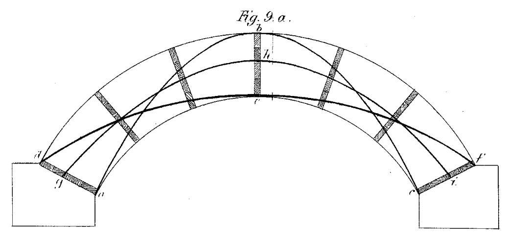
Through the mid to late 1800s, this was often seen as a problem, and there were many attempts to resolve it. Others recognised that it was not in fact a problem, and that if we can find one line of thrust that remains within the masonry for given dead and live loading, then the structure is safe. William Barlow was one of those who fully understood this. He presented a paper to the ICE, "On the Existence (Practically) of the Line of Equal Horizontal Thrust in Arches, and the Mode of Determining it by Geometrical Construction" where he demonstrated the fact with physical models. That illustrated below had timber slips in each joint that can be removed, and shows that the arch is stable, with the same shape, with different lines of thrust.
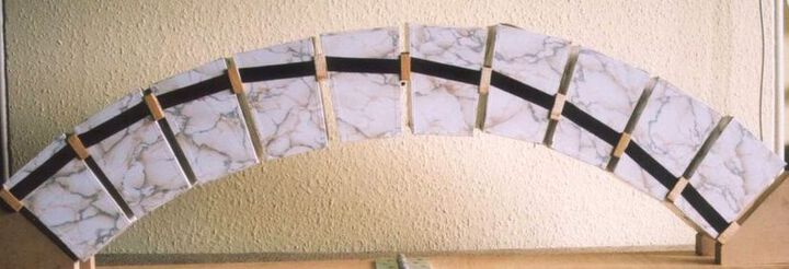
Bill made a model, following Barlow's scheme, which shows that the thrust in a symmetrical arch need not be symmetrical. Barlow may or may not have recognised this possibility.
The understanding that if we show that one line of thrust can fit within the material of the arch then the arch is stable was at last formalised by Heyman in the 1950s in terms of the plastic theorems, recently established by Baker for steel structures.
In software, we can use an optimisation routine to look for values for the unknowns that keep the thrust within the masonry. If any set of values can be found that does so, then by the "master safe theorem" of plastic theory, the arch will not collapse under the imposed loads.